Designing a voice recorder that snaps onto a Pixel 10
A slim voice-note recorder that magnetically attaches to the back of a Pixel 10, and the simulate-first workflow I used before ordering a custom board.
I wanted a physical record button for voice notes. Not an app I have to open and a screen I have to unlock, but a thin slab that sticks to the back of my phone and records when I press it. Later, on a computer, a local model turns the audio into text.
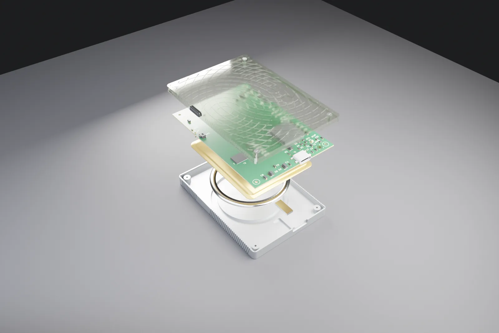
That became pixel-snap-voice: a one-off, rectangular recorder that attaches to a Google Pixel 10 with Pixelsnap (Qi2) magnets. This post covers what it is, the decisions that shaped it, and the workflow I used to design it without ordering a board I would regret.
What it is
The device is deliberately narrow in scope:
- Records 48 kHz, 16-bit, mono WAV files, about 346 MB per hour.
- Charges and dumps files over USB-C, appearing as a plain drive.
- Can start its own Wi-Fi network and serve its recordings to a browser, with a read-only WebDAV folder as well.
- Does no transcription on the device, has no Bluetooth file transfer, and does not charge wirelessly through the magnet ring.
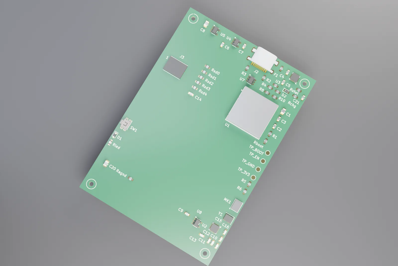
The hardware is an ESP32-S3 module, an ES8311 audio codec, an analog MEMS microphone, a pouch battery, and a chunk of SD NAND. The whole accessory fits in a 62 × 88 × 10.65 mm envelope, with the board itself at 59.6 × 85.6 mm.
Most of the interesting work was in deciding what to leave out. Each exclusion came from a concrete failure I could see coming:
- Transcription stays on the computer. Running a speech model on a microcontroller with no PSRAM is a project of its own. Dumping WAVs and running whisper.cpp locally is a small script, and it keeps audio off any cloud API.
- Bluetooth stays off. The S3 has no Bluetooth Classic, so file transfer would be BLE, which is slow for hours of audio.
- No wireless charging through the shell. That is a hard problem for a one-off board, and I did not want to take it on. The battery charges over USB-C.
Parts, and why not different parts
I spent more time than I expected on whether the ESP32-S3 was the right chip. The question I kept asking was: what is actually the bottleneck for audio quality? The answer was not the MCU.
The original design recorded from a digital MEMS microphone around 65 dBA SNR and had no way to play anything back. Switching to an nRF, STM32, or RP2350 would not raise that capsule's SNR, and it would throw away working USB mass-storage and ESP-IDF code. The real fixes were elsewhere:
- Add a codec. The ES8311 gives a proper analog front end with gain control, and it is the I2S master. The S3 has no audio PLL, so deriving exactly 48 kHz from its 160 MHz PLL is slightly off. A 12.288 MHz oscillator feeding the codec's master clock removes the problem at the source.
- Use a better capsule. An analog Infineon MEMS microphone at about 73 dBA, powered from a dedicated 2.8 V regulator so it never shares a rail with the noisy digital supply.
- Isolate the analog island. Analog microphones and codec ADCs suffer when they share a switching 3.3 V rail.
The module is the ESP32-S3-MINI-1U, the variant with an antenna connector rather than a PCB antenna. A PCB antenna would sit next to a steel magnet ring and an aluminum tray. The antenna is a small adhesive patch on the inside of the plastic lid instead.
Fitting a phone
The mechanical constraints came from the phone, not from me.
The Pixel 10 body is 152.8 × 72 × 8.6 mm, with a camera bar that adds about 3.4 mm. The accessory has to avoid the camera bar, seat on the Pixelsnap magnet array, and not spin. Magnets come from a commodity N52 ring plus a small clocking magnet that stops rotation. The side of the case facing the phone is a closed 0.85 mm non-ferrous skin, because Apple measures accessory magnetic flux through about that thickness, and the magnets sit in blind pockets behind it.
Two details I would have gotten wrong without writing them down:
- The tray is not steel. A steel tray shorts the magnetic path. The only steel is the plate already glued onto the bought ring.
- The record button is a side-push switch. Its plunger fires sideways into the wall on the phone's left side when the accessory is snapped on, so nothing has to poke through the phone-facing face.
The Pixelsnap center and the camera-bar dimensions I used are published defaults, not measurements. The design notes say plainly that someone has to caliper the real phone before a metal case is cut, and the CAD files do not pretend otherwise.
Simulate first
The point of this project was never the board by itself. It was getting to a board I trust before paying a fab. The repo is organized around checks that must pass first.
Firmware has a host build. The recorder core, meaning the state machine, WAV writer, and storage logic, builds two ways. On the ESP32 it runs under ESP-IDF. On a laptop it runs against a fake hardware layer with a fixture WAV, so I can test the state machine without any hardware attached.
The power path is simulated. An ngspice model covers USB through a PTC and charger to the battery and a 3.3 V rail, in two cases: USB with the battery unplugged, and battery only. It is a first-spin model, not a substitute for measuring the real board.
The mechanical envelope is a script. A Python checker verifies the keepouts: the accessory must not overlap the camera bar, the USB-C mouth must be on the wall at the phone's bottom edge, the microphone port must face a free edge, and the magnet ring must stay inside the outline.
One ship gate runs everything. check_gates.py runs the format checks, KiCad's design-rule check with schematic parity, pin and MCU checks, and placement checks. It then exports Gerbers, drill files, and the pick-and-place file, and generates the JLCPCB bill of materials. The rule for the order button is simple: it does not get pressed until that script is clean.
drc: 0 violations, 0 unconnected, 12 schematic-parity notes
kicad-cli gerbers, drills, pos and recorder-jlc.zip written to hardware/kicad/fab
check_gates: ok
A small example of why the gate earns its keep: JLCPCB will not machine-place a part with an empty order-code cell. The BOM is generated from the board, and a part with no LCSC number fails the script, so that mistake surfaces at my desk rather than in an email from the fab.
A lot of this repo was built with coding agents driving KiCad's Python API: generating schematic sheets, placing and routing, exporting fab files. That works because the gates are strict and machine-checkable. An agent that moves a footprint onto the wrong face of the board, or edits a BOM by hand, gets stopped by a script, not by my attention.
Where it stands
The board is designed, routed, and passes its gates. Every part has a fab order code that was checked against the fab's parts library, and the case parameters are set. The notes are open about what is not settled: the real Pixel measurements, power measurements on the first assembled board, and whether the 512 MB prototype storage is worth upgrading. On this storage chip the recorder fills in about 1.4 hours, well before the 7.5 hours the battery would last.
If you want to look closer, the architecture notes explain every electrical and mechanical decision, and the bring-up document describes how to prove the audio path on an off-the-shelf ESP32-S3 voice board before trusting a custom PCB. The code and design files are on GitHub.